
Abstract
Converting 54 V to a suitable 12 V is a challenging task that requires a new converter topology to develop an improved, high performance power supply. Additionally, it must have small dimensions to fit into the latest data center and hyperscale architecture, making a quarter brick small form factor highly desirable. This article will explore how an Analog Devices’ reference design stands out by addressing key concerns such as efficiency, power loss, thermal dissipation, and common footprint design. It will also discuss how the benefits and advantages can impact system applications.
Introduction
In today’s world of digital information and constant social connection, having a well-designed and efficient data center is essential. These data centers provide the networking, storage, and global connectivity we rely on. Keeping them running smoothly is crucial to avoid data interruptions and corruption. However, older data centers are struggling as they are operating near their limits with the market’s increasing demand of computing power, and their usage is continuously increasing rapidly every year. For example, the use of artificial intelligence as a large language model in terms of weekly active users has doubled in less than a year. This has led to a growing need for higher power density, which in turn will need more robust and high performance power converters.
As data centers scale up to support more powerful servers, networking equipment, and storage systems, they require higher power, which involves several stages of power conversion from the power transmission line down to the usable DC voltage level inside the rack. The legacy architecture in data centers is converting a rectified AC voltage down to 12 V DC, which will be the main power source inside the motherboards. However, 12 V DC architecture is becoming inefficient for main power delivery within the board. Increasing the input voltage to a 48 V supply allows for up to a 16× reduction in I2R losses across the PCB with considerably lower conversion losses and within the safety extra low voltage (SELV) level.
Therefore, an intermediate bus converter is a critical component in modern data center power architectures, which converts a 48 V voltage bus line from the primary power source, such as an uninterruptible power supply (UPS), to the existing intermediate bus voltage (5 V, 12 V architecture) and point-of-load (POL) regulators. This power supply is called an intermediate bus converter (IBC). IBCs come in various power capacities and sizes, with one common type being the quarter brick (QB) power supply.
A quarter brick power supply (QB PS) is a compact, efficient type of DC-to-DC converter module that plays a crucial role in modern power systems. It takes a high voltage DC input and converts it to a lower voltage that is ideal for powering a variety of peripherals and core processors inside the motherboard. The term quarter brick refers to its small, rectangular shape. These power supplies usually measure around 58.4 mm × 36.8 mm (2.3 inches × 1.45 inches) in a PCB area, with a height typically about 14.5 mm (0.57 inches). Despite the small size, a QB PS is highly efficient and can be easily integrated into existing power systems.
These power supplies are widely used in data centers, where their compact footprint and high efficiency make them ideal for use in server racks, network switches, ventilation systems, rectifiers, and battery backups. Their versatility and reliability make them a go- to solution for meeting the power needs of a modern electronic infrastructure. These power supplies usually operate with input voltage ranges of 40 V to 60 V, although there are variations available for different input voltages. They utilize a switching technique to efficiently regulate and convert the input voltage to a lower, regulated output voltage, typically from 9 V to 16 V. The output voltage can vary depending on the specific requirements.
Key Features of Quarter Brick Power Supplies Often Include:
High Efficiency
These power supplies are designed to maximize conversion efficiency. The reduction of conversion losses should be lower than the
I2R losses a legacy 12 V DC architecture will incur.
Wide Input Voltage Range
They can accept a broad range of input voltages, making them compatible with various power sources. A typical nominal input voltage range falls within 48 VDC to 54 VDC with an extended range of 40 V DC to 60 V DC.
Protection Mechanisms
They incorporate protective features such as overvoltage protection, overcurrent protection, short-circuit protection, and thermal shutdown to safeguard the power supply and the connected devices.
Thermal Management
Efficient heat dissipation is crucial for reliable operation. QB power supplies often include thermal management features such as heat sinks or integrated fans to regulate temperature.
Remote Sensing
Some models support remote sensing, which compensates for voltage drops along the output cables, ensuring accurate voltage regulation at the load.
PMBus and Advanced Control Features
Many QB power supplies offer advanced control capabilities, such as voltage trimming, remote on/off control, and synchronization with other power modules.
Scalability
The QB power supply should be easily scalable with minimum circuit adjustment, can be configured in parallel operation for different power demands, and can handle pre-biasing startup for hot swap capability.
When selecting a QB power supply, it is essential to consider factors such as input/output voltage requirements, load current, efficiency, operating temperature range, and specific industry certifications or standards applicable to your application. These features are available in a QB reference design, which is suitable for demanding applications that require stable and efficient power delivery.
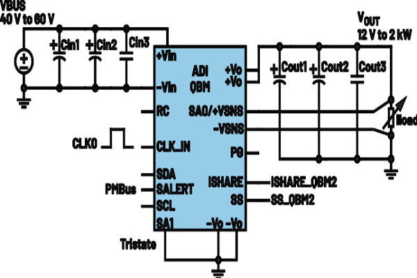
The key components of a QB power supply include an input filter, an output filter, some feedback control circuitry, and protection mechanisms that may be included in controller or power management ICs (PMICs). See Figure 1.
Advantages of a QB Power Supply
Compact Size
One of the primary advantages of a QB power supply is its compact form factor, which allows for efficient space utilization in applications where size is a constraint.
High Power Density
Despite their small size, QB power supplies offer high power density, enabling them to deliver significant power outputs.
Efficiency
With advancements in power conversion technologies, QB power supplies achieve high efficiency levels, reducing energy wastage and minimizing heat dissipation.
Thermal Management
QB power supplies often incorporate thermal management consideration, such as a flat baseplate that can be extended with a heat sink to ensure optimal operation and reliability in challenging thermal environments.
Reliability and Durability
These power supplies are designed to meet stringent industry standards, ensuring long-term reliability and durability even in harsh operating conditions.
Supply Resiliency
QB power supply pins are compatible between different manufacturers due to their common footprint package (CFP) to ensure resilient supply chain in production or ease of after-sale support in case of field failures.
Key Features of the LTC7822-Based QB Power Supply
Wide Input Voltage Range
QBM power supplies typically support a wide input voltage range, allowing for compatibility with various power sources.
Output Voltage Regulation
They provide precise and stable output voltage regulation, ensuring consistent performance across different load conditions.
High Power Density
The topology inherently reduces the size of the inductor with the addition of a switched capacitor section that halves the input voltage.
Scalable
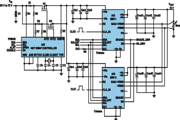
The topology is a current-mode power supply that can easily be paralleled by tying its soft start pin and compensation pin together. This reduces the complexity for parallel operation. Figure 2 shows an example of how each QB can be paralleled.
Protection Mechanisms
QBM power supplies incorporate protection features such as overvoltage protection (OVP), overcurrent protection (OCP), short- circuit protection (SCP), and thermal shutdown to safeguard against electrical faults and prevent damage to connected devices.
Reliability
The topology will inherently protect any next-stage downstream converters from high voltage DC because of the capacitive divider section. Even at failure of the top-most FET, a voltage divider will form to prevent failures at downstream converters.
Hybrid Converter as QB Topology
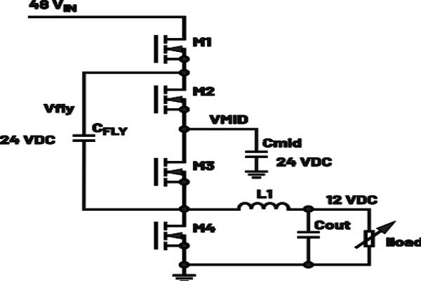
A QB power supply is a DC-to-DC converter that converts a 40 V to 60 V input voltage into a 12 V regulated output voltage. For this design, it makes use of a sophisticated architecture that combines a soft switching charge pump divider and synchronous step- down (buck) converter topology. The soft switching charge pump will halve the input voltage at very low conversion losses, so the buck section will only have to hard-switch at the VIN/2 level, or the voltage at the MID pin (Figure 3). This allows for efficient power conversion and a smaller inductor at the output. This comes at a trade-off of using a capacitor as another energy storage element, but
with proper rating and sizing the hybrid converter can outperform most of the conventional topology in the market. This article discusses how and why a hybrid converter is a very efficient topology.
A hybrid converter has a good balance between power delivery and power density for a quarter brick application. A typical fixed ratio switched capacitor is very efficient at high power density for low output power levels. As an example, the LTC7820 has an efficiency of up to 99% for 48 V to 24 V conversion at 28 mm × 28 mm PCB dimension (Figure 4). However, it is only designed for output power of about 300 W to 600 W.
To achieve higher output power without degrading efficiency, the design needs to consider paralleling another switched capacitor converter with more ceramic capacitors, taking up more PCB area. This will drastically hit power density and a second stage will be required for 24 V to 12 V DC conversion. Another switch capacitor topology can be used to create a single-stage 4:1 step-down ratio using a Dickson converter. It will require additional switches, but it is also limited by the same problem of needing more ceramic capacitors beyond 600 W, which affects scalability when the application demands more output current.
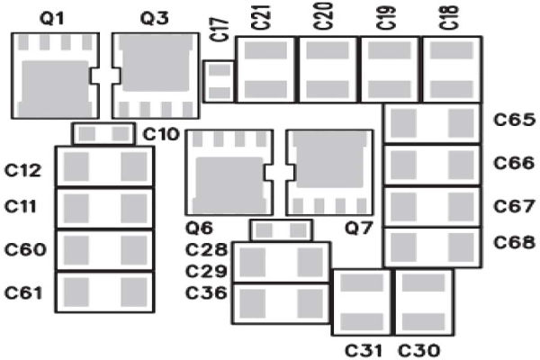
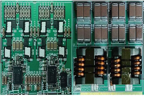
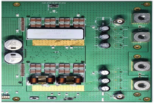
Using a regulated hybrid converter is a more suitable topology for power at the 1 kW level because it can deliver higher output current for limited PCB area. The switched capacitor section will convert the main input voltage line without handling most of the current conversion. The main output current conversion is delivered by the buck section, thereby reducing both fly capacitor footprints and inductor size. For a quarter brick form factor, the PCB area is critical because of the fixed dimension of 58.4 mm ×
36.8 mm. See Figure 5 for a reference component placement of a 4-phase hybrid converter in quarter brick dimension.
The LTC7822 is a high performance, 2-phase hybrid step-down DC-to-DC controller designed for high density power supply applications. This topology, shown in Figure 6, has two phases but significantly reduces the required capacitor elements per watts. This is possible because the fly capacitors of one phase serves two functions: (1) as a capacitor divider of its complementary phase, (2) and as one of the main storage elements of its own phase. This drastically reduces the number of mid capacitors needed per phase. A single chip of this device can deliver up to 1 kW of power, which is greater than any typical switched-capacitor topology for the same area.
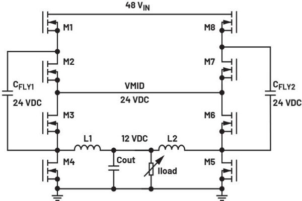
When the odd FETs (M1, M3, M5, M7) are turned on, the complementary FETs (M2, M4, M6, M8) are turned off. At this switch interval, CFLY1 is supplied by the input voltage and is connected in series via the VMID node with CFLY2. The two fly capacitors should have the same capacitance to have equal average voltage to reduce losses from current spiking when charge redistribution occurs.
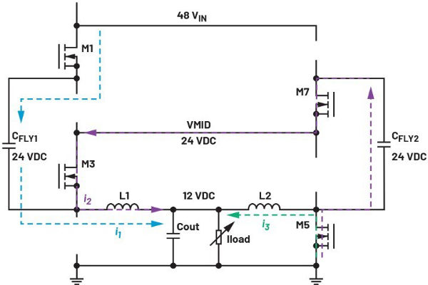
A careful selection of MOSFETs is also important to ensure that the bottom FETs (M4, M8) will operate within the safe operating area (SoA). The maximum current that a bottom FET will experience is about 1.5× times its average phase current because of two mesh currents shared through the common MID node. As an example: the current when L2 is de-energized will flow through M5. But since CFLY2 is also supplying part of the energy to L1 via M3, its return path will also be through M5. See Figure 7 for the current flow direction.
Coupled Inductors in Intermediate Bus Converters
A coupled inductor is another excellent technology to incorporate with a hybrid converter for intermediate bus applications due to the integer ratio conversion. A 48 V to 12 V conversion will have 50% duty cycle, which makes the buck section operate at a notch for a 2-phase coupled inductor design. Even for a wider 40 V to 60 V (typical) input voltage range, it can still benefit from using a coupled inductor instead of a discrete inductor (DL). Figure 8 shows the normalized current ripple comparison between a discrete inductor and coupled inductor with different phases.
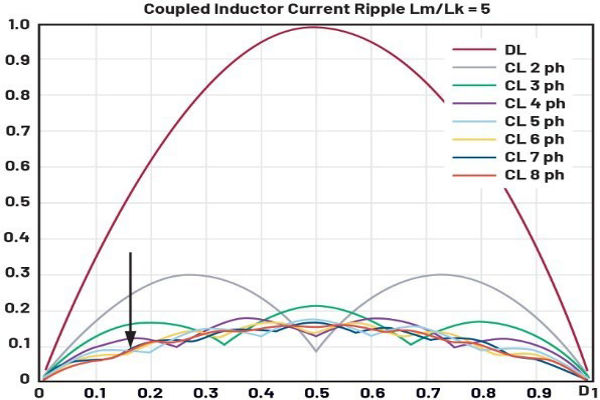
As seen in Figure 8, the current ripple is minimized at 50% duty cycle for a 2-phase coupled inductor design. Notice that the benefit of coupled inductors is not the same across different duty cycles. Different phases have different notch locations where the reduction of current ripple is maximized. So, it is important to consider the input voltage range and target output voltage of the quarter brick design. For example: a hybrid converter with a 4:1 step-down ratio should use a 2-phase design to maximize the coupled inductor’s current ripple reduction, but a designer may need to consider using a single 4-phase design for an 8:1 step- down ratio because of the notch at 25% duty cycle. See Figure 9 for an example of a single 4-phase coupled inductor.
The most important impact of using a coupled inductor in a quarter brick design is its significant reduction in the size of magnetic components while retaining efficiency performance. This enables the hybrid converter to fit in a quarter brick area while still delivering very high output power at competitive efficiency.
Applications of Quarter Brick Power Supply
QB power supplies find applications in various industries and sectors, including the following.
Telecommunications are commonly used in telecom infrastructure, data centers, and networking equipment to power communication systems and network switches.
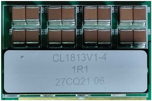
QB power supplies are suitable for industrial automation applications such as motor drives, robotics, and control systems. Using a hybrid converter-based quarter brick power supply is suitable for different output voltage step-down ratios. ADI’s discrete quarter brick reference design makes it easier to include multiple coupled inductor footprints available to evaluate up to two different output voltage levels, or parallel them together to test at higher output current requirements. See Figure 10 for the quarter brick section
Conclusion
Older data centers are struggling to meet the increasing demand for computing power, especially with the rapid growth of artificial intelligence. To address these challenges, modern data centers are adopting new designs with higher power density, such as the 48 V architecture, which significantly reduces power losses compared to the traditional 12 V architecture. A key component in this transition is the intermediate bus converter, specifically the quarter brick power supply. These compact, efficient DC-to-DC converters are essential for converting high voltage DC input to lower voltages required by various peripherals and core processors.
The QB power supplies provide a streamlined, high performance power solution suitable for diverse applications. Renowned for their compact design, energy efficiency, and robust reliability, these power supplies boast superior power density, accurate voltage regulation, and advanced protective features, making them an essential component across various industries. They are designed to maximize space utilization, ensure reliable operation, and meet the power needs of modern electronic infrastructure.
Analog Devices’ hybrid converters, and the latest LTC7822, deliver key advantages for powering data centers while offering high efficiency, robust performance, and advanced control features. The LTC7822’s ability to be optimized for strict form factor, together with coupled inductors, makes it a competitive topology choice for high power applications. Enhanced reliability and reduced operational costs make it an ideal solution for efficient and dependable data center power management.
The next part of this series will discuss the comprehensive evaluation for the LTC7822-based quarter brick power supply and the data gathered to provide the electrical and thermal performance, as well as the proper component selection for high power application.


